Brakes - what do they do?
The simple answer : they slow you down.
The complex answer : brakes are designed to slow down your vehicle but probably
not by the means that you think. The common misconception is that brakes squeeze
against a drum or disc, and the pressure of the squeezing action is what slows
you down. This in fact is only part of the reason you slow down. Brakes are
essentially a mechanism to change energy types. When you're travelling at speed,
your vehicle has kinetic energy. When you apply the brakes, the pads or
shoes that press against the brake drum or rotor convert that energy into
thermal energy. The cooling of the brakes dissipates the heat and the
vehicle slows down. This is all to do with The First Law of Thermodynamics,
sometimes known as the law of conservation of energy. This states that energy
cannot be created nor destroyed, it can only be converted from one form to
another. In the case of brakes, it is converted from kinetic energy to thermal
energy.
Thermodynamics, brake fade and drilled rotors.
 If you ride a
motorbike or drive a race car, you're probably familiar with the term brake
fade which is used to describe what happens to brakes when they get too hot.
A good example is coming down a mountain pass using your brakes rather than your
engine to slow you down. By the First Law of Thermodynamics, as you start to
come down the pass, the brakes on your vehicle heat up, slowing you down. But if
you keep using the brakes, the drums or discs and brake pads will stay hot and
get no chance to cool off. The next time you try to brake, because the brake
components are already so hot, they cannot absorb much more heat. Once they get
to this stage, you have to look at the brake pads themselves. In every brake pad
there is the friction material which is held together with some sort of resin.
Once this lot starts to get too hot, the resin holding the pad material together
starts to vapourise, forming a gas. That gas has to have somewhere to go,
because it can't stay between the pad and the rotor, so if forms a thin layer
between the two trying to escape. The result is very similar to hydroplaning
while going too fast in the rain; the pads lose contact with the rotor, thus
reducing the amount of friction. Voila. Brake fade.
If you ride a
motorbike or drive a race car, you're probably familiar with the term brake
fade which is used to describe what happens to brakes when they get too hot.
A good example is coming down a mountain pass using your brakes rather than your
engine to slow you down. By the First Law of Thermodynamics, as you start to
come down the pass, the brakes on your vehicle heat up, slowing you down. But if
you keep using the brakes, the drums or discs and brake pads will stay hot and
get no chance to cool off. The next time you try to brake, because the brake
components are already so hot, they cannot absorb much more heat. Once they get
to this stage, you have to look at the brake pads themselves. In every brake pad
there is the friction material which is held together with some sort of resin.
Once this lot starts to get too hot, the resin holding the pad material together
starts to vapourise, forming a gas. That gas has to have somewhere to go,
because it can't stay between the pad and the rotor, so if forms a thin layer
between the two trying to escape. The result is very similar to hydroplaning
while going too fast in the rain; the pads lose contact with the rotor, thus
reducing the amount of friction. Voila. Brake fade.
The typical symptom of this would be to get the vehicle to a stop and wait for a
few minutes. As the brake components cool down, their ability to absorb heat
returns, the pads cool off which means they have more chance to heat up again
before the resin vapourises, hence the next time you use the brakes, they seem
to work just fine.
So how do the engineers design brakes to reduce or eliminate brake fade? You
give that vapourised gas somewhere to go. Cross-drilled or grooved brake rotors.
While grooving the surface may reduce the specific heat of the rotor, its effect
is negligable in the grand scheme of things. The rotors will heat up to cool
down no faster or slower. However, under heavy braking once everything is hot
and the resin is vapourising, the grooves give the gas somewhere to go, so the
pad can continue to contact the rotor, allowing you to stop.
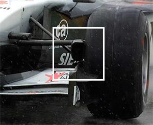
The whole understanding of the conversion of energy is critical in understanding
how and why brakes do what they do, and why they are designed like they are. If
you've ever watched Formula-1 racing, you'll see the front wheels have huge
scoops inside the wheel pointing to the front (see the picture on the right).
This is to duct air to the brake rotors to help them cool off because in
Formula-1 racing, the brakes are used viciously every few seconds and spend a
lot of their time trying to stay hot. Without some form of cooling assistance,
the brakes would be fine for the first few corners but then would fade and
become near useless by half way around the track.
Rotor technology.
If a brake rotor was a single cast chunk of steel, it would have terrible heat
dissipation properties and leave nowhere for the vapourised gas to go. Because
of this, brake rotors are typically modified with all manner of extra design
features to help them cool down as quickly as possible as well as dissapate any
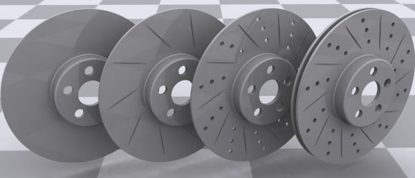
gas from between the pads and rotors. The following diagram shows some examples
of rotor types with the various modification that can be done to them to help
them create more friction, disperse more heat more quickly, and ventilate gas.
From left to right.
1. Basic brake rotor. 2. Grooved rotor. The grooves give more bite and thus more
friction as they pass between the brake pads They also allow gas to vent from
between the pads and the rotor. 3. Grooved, drilled rotor. The drilled holes
again give more bite, but also allow eddy currents to blow through the brake
disc to assist cooling and ventilating gas. 4. Dual ventilated rotors. Same as
before but now with two rotors instead of one, and with vanes in between them to
generate a vortex which will cool the rotors even further whilst trying to
actually 'suck' any gas away from the pads.
Big rotors.
You know I've been drumming into you the whole mechanism that causes you to
stop? Here's another reason. Sports cars and race bikes typically have much
bigger discs or rotors than your average family saloon car. The reason? Heat and
friction. A bigger rotor has more material in it so it can absorb more heat.
More material also means a larger surface area, which as well as meaning more
area for the pads to generate friction with, also translates to better heat
dissipation. ie. bigger rotors = better stopping power.
Taking it one step further, composite brake rotors, as found on high-end
Ferraris, the McLaren F1, and most Formula-1 race cars, are even better again at
heat transfer.
The different types of brake.
All brakes work by friction. Friction causes heat which is part
of the kinetic energy conversion process. How they create friction is down to
the various designs.
Bicycle wheel brakes
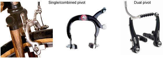
I thought I'd cover these because they're about the most basic
type of functioning brake that you can see, watch working, and understand. The
construction is very simple and out-in-the-open. A pair of rubber blocks are
attached to a pair of calipers which are pivoted on the frame. When you pull the
brake cable, the pads are pressed against the side or inner edge of the bicycle
wheel rim. The rubber creates friction, which creates heat, which is the
transfer of kinetic energy that slows you down. There's only really two types of
bicycle brake - those on which each brake shoe shares the same pivot point, and
those with two pivot points. If you can look at a bicycle brake and not
understand what's going on, the rest of this page is going to cause you a bit of
a headache.
Drum brakes - single leading edge
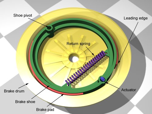
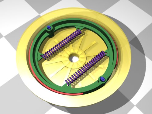
The next, more complicated type of brake is a drum brake. The
concept here is simple. Two semicircular brake shoes sit inside a spinning drum
which is attached to the wheel. When you apply the brakes, the shoes are
expanded outwards to press against the inside of the drum. This creates
friction, which creates heat, which transfers kinetic energy, which slows you
down. The example below shows a simple model. The actuator in this case is the
blue elliptical object. As that is twisted, it forces against the brake shoes
and in turn forces them to expand outwards. The return spring is what pulls the
shoes back away from the surface of the brake drum when the brakes are released.
See the later section for more information on actuator types.
The "single leading edge" refers to the number of parts of the
brake shoe which actually contact the spinning drum. Because the brake shoe
pivots at one end, simple geometry means that the entire brake pad cannot
contact the brake drum. The leading edge is the term given to the part of the
brake pad which does contact the drum, and in the case of a single
leading edge system, it's the part of the pad closest to the actuator. The
diagram below shows what happens as the brakes are applied. The shoes are
pressed outwards and the part of the brake pad which first contacts the drum is
the leading edge. The action of the drum spinning actually helps to draw the
brake pad outwards because of friction, which causes the brakes to "bite". The
trailing edge of the brake shoe makes virtually no contact with the drum at all.
This simple geometry explains why it's really difficult to stop a vehicle
rolling backwards if it's equipped only with single leading edge drum brakes. As
the drum spins backwards, the leading edge of the shoe becomes the trailing edge
and thus doesn't bite.
Drum brakes - double leading edge
The drawbacks of the single leading edge style of drum brake can
be eliminated by adding a second return spring and turning the pivot point into
a second actuator. Now when the brakes are applied, the shoes are pressed
outwards at two points. So each brake pad now has one leading and one trailing
edge. Because there are two brake shoes, there are two brake pads, which means
there are two leading edges. Hence the name double leading edge.
Disc brakes
Disc brakes are an order of magnitude better at stopping
vehicles than drum brakes, which is why you'll find disc brakes on the front of
almost every car and motorbike built today. Sportier vehicles with higher speeds
need better brakes to slow them down, so you'll likely see disc brakes on the
rear of those too.
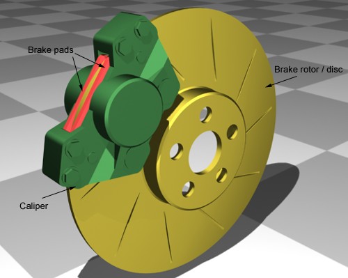
Disc brakes are again a two-part system. Instead of the drum, you have a disc or
rotor, and instead of the brake shoes, you now have brake caliper assemblies.
The caliper assemblies contain one or more hydraulic pistons which push against
the back of the brake pads, clamping them together around the spinning rotor.
The harder they clamp together, the more friction is generated, which means more
heat, which means more kinetic energy transfer, which slows you down. You get
the idea by now.
Standard disc brakes have one or two cylinders in them - also
know as one or two-pot calipers. Where more force is required, three, or more
cylinders can be used. Sports bikes have 4- or 6-pot calipers arranged in pairs.
The disadvantage of disc brakes is that they are extremely intolerant of faulty
workmanship or bad machining. If you have a regular car disc rotor which is off
by so much as 0.07mm (3/1000 inch) it will be Hell when you step on the brakes.
That ever-so-slight warp or misalignment is going to spin through the clamped
calipers at some ungodly speed and the resulting vibration will make you wonder
if you're driving down stairs. To combat this problem, which is particularly
critical on motorbikes, floating rotors were invented.
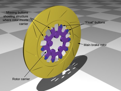
The floating rotor.
Standard brake rotors are cast in a single piece which bolts directly to the
wheel or drive plate. If the mounting surface of your wheel or drive plate isn't
perfectly flat, you'll get vibration at speed. Floating rotors are typically
cast in two pieces - the rotor and the carrier. The carrier is bolted to the
wheel and the rotor is attached to the carrier using float buttons. The other
method of floating a brake rotor is to have the rotor bolted directly to the
wheel itself without a carrier, but the bolts have float buttons built into
them.
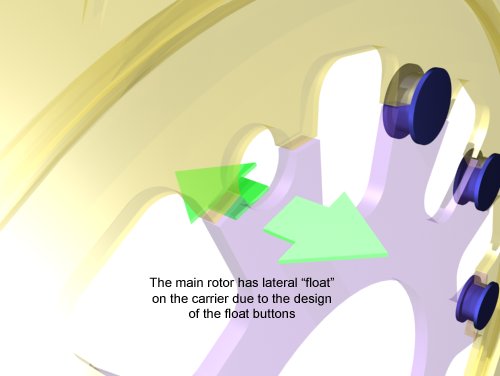
These buttons allow the brake rotor some freedom to move
laterally, but restrict the angular and rotational movement as if they were
bolted directly to the wheel. This slight lateral motion which can be less than
0.03mm, is just enough to prevent vibration in the brake system. Because the
calipers are mounted solidly, and warping or misalignment in the wheel or brake
rotor mounting face can be compensated for because the rotor will "float"
laterally on the float buttons. This side-to-side vibration is separated from
the carrier by the float buttons themselves, so none of the resulting motion is
transferred into the suspension or steering. Clever eh? The rendering below
shows an extreme close-up of the brake disc shown above. I've rendered the
components slightly transparent so you can see what's going on.
 Radial calipers / radial brakes.
Around the year 2003, motorbikes started to hit the showrooms with a new feature
- radial brakes. The magazines and testers will all tell you that radial brakes
make the bike stop quicker. Not true - they have nothing to do with stopping
power and everything to do with the design of the front forks of the bike. More
and more bikes are coming out with upside-down forks. ie. instead of the fat
canister part of the fork being at the bottom of the assembly, it's at the top.
This means that the fork pistons are now the part of the suspension with the
wheel attached to them. It also means that it's impossible to put a stiffening
fork brace down there now because the brace would need to move with the wheel,
and the length of the fork pistons precludes that.
The stiffness of the front end is now entirely dependent on the size of the
front axle. Bigger axle = stiffer front end. A side-effect of this design was
that traditionally-mounted brake calipers could cause a lot of vibration in the
steering because of flex between the wheel (with the brake disc bolted to it),
and the fork leg (with the caliper). The slight tolerance allowed by floating
brake rotors couldn't compensate for the amount of flexing in the forks. To
reduce the brake-induced fork vibration, the brake calipers were moved around
the rotors so that they fell into the radial line of the wheel. This is because
there is less lateral flex at that point, which means less or no vibration. It's
interesting to note that car brakes have been radially mounted for decades.
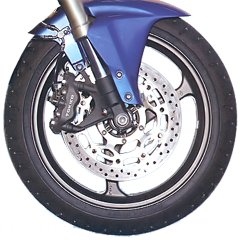
The image on the right here shows radially mounted brake calipers, and floating
brake rotors on a modern race-inspired motorbike.
Brake pad compounds.
Just a quick word on brake pad compounds. Most pads used to use
asbestos but we all know what that stuff is like. Today they use all manner of
combinations of materials.
The pads themselves are made up of a friction material bonded to the backing
plate. The brake caliper piston pushes against the backing plate and the
friction material is pushed against the brake rotor. The material combinations
typically fall into the following broad categories now.
- Organic
- These pads are well-suited for street driving because they wear well, are
easy on the ears, don't chew up the rotors and don't spew dust everywhere.
They're favoured for your average family saloon because they work well when
they're cold. Of course the drawback is that they don't work so well when they
get hot.
- Semi-metallic / sintered
- This is a good compromise between street and track. These seem to be the
pad of choice for sportier vehicles such as the Subaru Impreza WRX. They won't
work as well as organic pads when they are cold, so you need to be a bit wary
of the first couple of stops. Conversely they do work well when hot.
Occasionally the weak link in semi-metallic pads is the bonding material that
holds the friction pad to the backing plate. There have been occasions where
the friction material has come away completely. That's infrequent though.
- Metallic
- These pads are typically reserved for racing or the extremely rich. They
squeal and dust like crazy, are hard on rotors and don't work well when cold.
- Ceramic
- Ceramic pads still have metal fibers (about 15% vs. about 40% for
semi-metallic) but they are copper instead of steel and therefore cause less
wear and transfer heat better. They don't fade as easily as other pads, cool
faster, last longer, and are effectively silent, as the sound they genereate
is outside of the human range of hearing. Dogs will go crazy thought. The dust
created by ceramic pads is also very light in color so your wheels look
cleaner.
Brake squeal.
Squealing brakes are a sign of one of two things : the friction
material is all gone and you're jamming the backing plate against the brake
rotor, or the fit of the brake pad against the caliper piston isn't as snug as
it could be. Either way, the squealing is the result of an extremely
high-frequency vibration between the pad, the caliper piston and the brake
rotor. Some vehicles have problems with squealy brakes right from the factory.
In those cases, simply changing brake pad manufacturer can often cure the
problem as the different pads will have a slightly different harmonic frequency,
which is harder to attain. A classic example was one of the BMW R1100 touring
bikes. From the factory, they'd squeal like crazy, and BMW redesigned the brake
calipers and rotors a couple of times until they finally just switched to a
different brand of pads and the problem vanished.
Brake actuators.
Brakes are all well and good, but you need some method of
applying them in order for them to work. The method by which the force from your
hand or foot reaches the brake itself is all to do with the brake actuator
system.
Cable-operated
This is about as basic as you get. A cable is connected to a
lever at each end. You press on one lever with your foot or squeeze it with your
hand, and it pulls the lever at the other end. On the back of the brake-end
lever there's an elliptical cam which rotates inside a circular cup in the brake
shoe. As the long axis of the ellipse rotates, it forces the brake shoes to move
apart. In the case of a bicycle brake, the brake-end of the cable just pulls the
two calipers together.
Solid bar connection
One step up, and found on the rear brake of older motorbikes,
the solid bar connection. This allows the use of mechanical advantage (see
below) to amplify your force on the pedal or lever before it gets to the brakes
themselves. Typically these systems are used on drum brakes with the elliptical
actuator described above. The disadvantage of this system is that it needs hinge
and pivot points that match the position of the suspension components. If
they're not present, going over a bump could put the brakes on as the suspension
moves relative to the lever.
Single-circuit hydraulic
Another step up and we get to the type of brake system used on
most cars and motorbikes today. Gone are the cables and bars, replaced instead
with a system of plungers, reservoirs and hydraulic fluid. Single-circuit
hydraulic systems have three basic components - the master cylinder, the slave
cylinder and the reservoir. They're joined together with hydraulic hose and
filled with a non-compressible hydraulic fluid (see brake fluid below). When you
press your foot on the brake, or squeeze the brake lever, you compress a small
piston assembly in the master cylinder. Because the brake fluid does not
compress, that pressure is instantaneously transferred through the hydraulic
brake line to the slave cylinder where it acts on another piston assembly,
pushing it out. That slave assembly is either connected to a lever to activate
the brakes, or more commonly, is the brake caliper itself, with the slave
cylinder being the piston that acts directly on the brake pads. Because of the
arrangement of the slave cylinder, heat from the brakes can be transferred back
into the brake fluid.
Dual-circuit hydraulic
Dual-circuit hydraulic systems are available on high-end luxury
vehicles and newer motorbikes, in particular BMW bikes. These have two separate
circuits. One is the command circuit - that's the one you act on with your hand
or foot. The second is a separate circuit controlled by an onboard computer, and
that's the one which is actually connected to the brakes. As you apply the
brakes, you're sending a pressure signal via the command circuit to the brake
computer. It measures the amount of force you're applying, and using a servo /
pump system, applies the same force to the secondary circuit to activate the
brakes. If you do something stupid like trying to slam on the brakes at 100mph,
the computer will realise that this would result in a skid or spin, and will not
send the full pressure down the secondary circuit, instead deciding to use it's
speed and ABS sensors to determine the optimal brake pressure to maintain
control of the vehicle. The advantage of a dual-circuit system is that the
command circuit never gets heat transferred into it because it is totally
separated from the brakes themselves. The disadvantage of course is that you now
have two hydraulic circuits to maintain.
Brake-by-wire
The most advanced system of brakes to date are brake-by-wire.
These are a direct copy of Formula-1 racing brakes and are very similar to the
dual-circuit hydraulic system described above, but instead of the command
circuit being hydraulic, its replaced with electronics. The brake pedal or lever
is connected to a hypersensitive rheostat (measures electrical resistance). The
more you push it, the greater the electrical signal sent to the brake computer.
From there on, it performs just like the secondary circuit described above. The
advantage to this system is that the brake pedal or lever can be placed just
about anywhere you like as it no longer is encumbered by the plumbing that goes
with a hydraulic circuit. To combat driver complaints of "lack of feel" in the
brakes, most brake-by-wire systems have a reverse feedback loop built in. This
measures the pressure being applied to the brakes on the secondary circuit, and
actuates an electrical resistor in the pedal or lever assembly to provide
resistance. This is needed because there is no physical connection to any
part of the brake system at all.
Mechanical advantage - why you can stop a 2-ton car with one foot.
If you did any sort of physics classes when you were back in
school, you might remember something called mechanical advantage. In its most
basic form, mechanical advantage is the ratio of force-in to force-out in a
mechanical system. Mechanical Advantage = Effort Torque/Load Torque.
For example a 20kg weight 1 metre from a pivot can lift a 40kg weight 0.5m from
the pivot on the other side. The effort torque and load torque calculations are
to do with force in Newtons and distance from pivot point. Hence torque is
measured in Newton-metres, or Nm. Another popular notation is lbf.ft -
pound-force-feet, commonly referred to as foot-pounds. 1 Newton-metre is
equivalent to 0.737 foot-pounds.
The diagram below shows a simple lever system on a pivot. The load torque is
20Nm, and the effort torque is also 20Nm. Mechanical advantage = effort / load,
which in this case is 20 / 20, which is 1. ie. the system is balanced.

Now imagine increasing the weight on the effort side to 30kg
instead of 20kg, but leaving everything else the same. The load torque is still
20Nm, but the effort torque is now 30Nm. Mechanical advantage = effort / load,
which is 30 / 20, which is 1.5. Any mechanical advantage value larger than 1.0
means that the effort has the advantage. In this case, a 30kg weight which is
lighter than the 40kg load, is able to lift it off the ground.
If you now take your new-found / remembered knowledge about
physics and look at the simple lever brake system, you'll realise how it's
possible to generate enough force using your foot to stop a car or motorbike.
Look at this diagram of the lever-operated cam brake.
This system has 4 levers in it. The middle two have no
mechanical advantage as the levers are connected the same distance from the
pivot in each case. However, look at the pedal. The values I've put in are
arbitrary but they serve the purpose. On the pedal we have some amount of force
20cm from the pivot, but the other end of the lever is only 5cm from the pivot.
This gives us a mechanical advantage of 4 on the brake lever (20cm / 5cm).
At the other end, the lever attached to the cam is still a lever system - it's
just bent. The input lever is 10cm long but the cam is only 4cm across - or 2cm
to the tip from the pivot. So at the brake cam we have a mechanical advantage of
5. (10cm / 2cm). So across this entire system, we have a total mechanical
advantage of 20 - 4 from the brake pedal and 5 from the lever and cam. Apply
force to this little system and be amazed. The units of force used are
irrelevant - they're multiplied just the same. To use easier-to-comprehend
values, let's imagine that when you're braking, your foot is pushing on the
brake pedal with about 60pounds of force - 27Kg. Through the brake pedal, that
is amplified 4 times to 240pounds, and through the lever and cam its amplified a
further 5 times from 240pounds to 1200pounds. You pushed the pedal with 60pounds
of force, but the cam inside the drum brake is being forced out against the
brake drum with 1200pounds of force - about 544Kg. Sweet.
Mechanical advantage as applied to hydraulics.
Most braking systems now use hydraulics. This is a slight change
in the equation but the concept of mechanical advantage still exists, this time
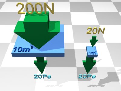
by the use of pressure equations. Pressure = force / area. If you apply 20
Newtons of pressure to 1m², it's the same as applying 200 Newtons to 10m². Why?
Because 20 Newtons of force divided by 1m² of area generates 20 Pascals of
pressure. Similarly, 200N / 10m² is also 20Pa.
If you now think of that in terms of a hydraulic braking system,
it becomes clear how mechanical advantage works for you. Brake fluid is
incompressible - it has to be. This is good because it makes calculation for
hydraulic brake systems quite easy - you can eliminate the internal pressure
from the equation.
Split the system into two parts - input and output - the brake pedal and the
brake caliper piston.
For each part, Pressure = Force / Area. The Pressure is the same at all points
in the system, so some basic algebra gives a simple formula:
Using our previous example, we apply 60pounds (27Kg) of input
force to the brake pedal. This is attached to a master piston which (for
example) is 1.25cm across - ie. it has a surface area of 0.000491m² (remember
your maths? area = PI x r²). At the other end of the system is the caliper
piston, which for example is 2cm across - ie. it has a surface area of
0.001257m². Using our sparkly new formula, the output force from the caliper
piston is
60 x (0.001257m² / 0.000491m²) Get your calculator out and that comes out to
154pounds (69.8Kg) - more than double the force at the brake pedal. The ratio of
output area to input area is sometimes referred to as the area differential.
So that, my friend, is why you can stop a speeding vehicle with a single foot.
Power Brakes and master cylinders.
Power brakes (also known as power assisted brakes) are designed
to use the power of the engine and/or battery to enhance your braking power.
Whilst you can generate a fair amount of force using your foot, using systems
from elsewhere in the car to help you apply even more force means that you get
more powerful brakes as a result.
The four most common types of power brakes are: vacuum suspended; air suspended;
hydraulic booster, and electrohydraulic booster. Most cars use vacuum suspended
units (vacuum boosters). In this type of system, when you press the brake pedal,
the push rod to the master cylinder opens a vacuum control valve. This allows
vacuum pressure (normally from the intake manifold) to "suck" on a diaphragm
inside the vacuum assist unit. This extra vacuum suction helps you to produce
more force at the pedal end of the brake system.
You'll notice in the image below (which I scurrilously had to modify from
someone else's site - if that's you, I apologise), that the master cylinder has
two brake circuits and two master pistons. These circuits are separate and are
typically connected to the front-left and rear-right wheel on the first circuit,
and the front-right and rear-left wheels on the secondary circuit. This means
that if one circuit fails, the second one will still work and it will still
apply braking force to the front and rear of the car.
Hydraulic booster systems usually utilise pressure from the
power steering system to augment pressure on the master brake cylinder.
Electrohydraulic booster systems use an electric motor to pressurize the
hydraulic system downwind of the brake pedal which has the effect of amplifying
the internal pressure in the whole system.The advantage to this system is that
as long as you have battery power, you have power brakes even if the engine
fails. With vacuum-assist brakes, no engine means no assistance.
If you're curious about how power brakes work, go out to your car and with the
engine off, step on the brakes. They'll have a slightly solid, almost wooden
feel to them. Turn the engine on and do it again and you'll notice a lot less
back-pressure on the pedal. This is the power assist which is making it easier
for you to depress the pedal.
One last thing about brake master cylinders : they cost an absolute bomb to
replace. If you find yours is leaking, patching it up is not an option. Brand
new master cylinders can go for around $1500 without labour costs.
Remanufactured ones come in slightly cheaper at around $900. Bear that in mind
when your 20 year old beater develops a leak - it's probably cheaper to buy
another used car than to replace the master cylinder.
Anti lock Braking Systems - ABS
Stop without skidding, and maintain control of the vehicle.
That's the premise of ABS. It was first introduced in the 1980's and has been
undergoing constant refinement ever since. The system is typically comprised of
4 ABS rings, 4 sensors, an ABS computer and a pressure-management system in the
brake line. The ABS rings are attached either to the wheels, or more often, to
the brake discs. They look like a notched ring - see the image below.
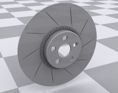
The sensors are magnetic field sensors which are held very close
to the ABS rings and can detect the slight change in magnetic field as the teeth
on the ring pass them. The pulsing field tells the ABS computer that the wheels
are spinning, and how fast they're spinning.
When you brake, the wheel rotation starts to slow down. The ABS computer
"listens" to the input from the sensors and can detect if one wheel is slowing
down much quicker than the others - the precursor to the wheel locking up. This
all happens in milliseconds, by the way. When the computer detects this
condition, the pressure regulator interrupts the pressure in the brake lines by
momentarily reducing the pressure so that the brakes give the wheels a chance to
keep spinning rather than locking up. The computer then instructs the regulator
to re-apply full pressure and again measures the wheel rotation. This
on/off/measure cycle happens around 15 to 30 times a second. If the ABS kicks
in, you'll feel it through the brake pedal as a vibration because the pulsing in
the brake circuit affects all the components.
Newer generation ABS systems
As technology marches on, so does the control / feedback system
used in ABS. It used to be the case that any single wheel approaching lockup
would cause the ABS system to pulse the brake pressure for all the wheels. With
the latest vehicles, the ABS computer is connected to 4 pressure regulators
instead of just the one. This means it can selectively apply pulsed braking only
to the wheel(s) that need it. So if three of the tyres are gripping well, but
the front-left is beginning to skid, the ABS can unlock the front-left brake and
pulse it to try to regain grip. It's all very James Bond.
ABS and skid control
The biggest misconception about ABS is that it will make you
stop faster. This is absolutely not true. ABS has nothing to do with stopping
power and everything to do with maintaining control of your vehicle, be it a
car, truck or motorbike. The problem with skidding whilst braking is that it
removes you from ultimate control of where the vehicle is going. On a motorbike,
skidding invariably causes highsides, flips and general thoughts of "huh?" to
the rider as he's flying through the air towards certain pain. In a car or
truck, skidding stops the vehicle from going where you want it to, and instead
makes it straight-line based on the camber of the road, the speed of the vehicle
and how much damage it can do to your insurance policy.
Skidding is caused because the wheels lock up. Once they stop rotating, the
tyres can no longer grip the road surface and begin to skate across it. When
that happens, it really makes no difference where the steering is pointing
because without grip, steering is useless.
With ABS, the idea is that the wheels don't ever lock up, so you still have
control over the steering. The wheels keep going around, so the tyres keep
gripping, so the steering is effective. That's where ABS gets its name -
Anti-Lock Brakes.
The bone of contention with ABS
So many people think ABS gives them a license to drive faster,
because they mistakenly believe that ABS will get them out of any situation.
It's yet another technical placebo that has been put into vehicles which is
making the standard of driving worse. The more gadgets and "driver aids" that
get put into a car, the worse the drivers become because they live in a
pink-spectacled world where they believe that the car will get them out of any
problem they cause. It bothers me so much I have a "rant" page dedicated to it
here :
Nanny Cars.
Personally I don't like ABS. I don't like the idea of a computer interrupting
the connection between my right foot and the brakes. It also doesn't work worth
a damn on gravel or in the snow. With regular brakes, in the snow, you can jam
them on and at least stand a chance of the tyres digging in and finding the road
surface. With ABS the system will just take the brakes off and you'll skate
merrily along on the snow with no chance of slowing down.
The hidden gremlin of ABS - what they don't advertise.
If you look at the statistics for crashes, a large percentage of
them are "fender benders" - low-speed impacts that only do a little damage and
so slow that the vehicle occupants are in no danger. Less than 15mph normally.
I'll give you one guess what the typical "minimum activation speed" is for ABS.
That's right. Your average ABS system is useless much below 15mph. Seriously.
Try it yourself. Find an empty road on a slight downhill grade - even better if
its on a dewy morning. Run your ABS-equipped car up to about 15mph and jam on
the brakes as hard as you can. The car will skid to a stop and the ABS system
will remain totally silent.
Aftermarket ABS systems
To the best of my knowledge, there's no such thing. A few years
back a couple of companies tried to market what they called ABS systems that
could be retrofitted to any vehicle. The product was a cylinder with a
pressure-relief valve in it. The idea was that you inserted this system into the
brake circuit somewhere. When you stomped on the brakes - symptomatic of locking
up the wheels - the pressure relief valve opened and bled off some brake fluid
into the cylinder, thus lowering the braking pressure being sent to the wheels.
The idea was to take the "spike" off the initial push of the brake pedal so it
wasn't ABS at all. The whole idea of putting something like this into a brake
circuit makes me shudder - I wouldn't want to be the person trying to get their
insurance and medical claims through after an accident when the investigators
found one of these contraptions in their brake line!
Brake hoses - not just rubber.
Obviously with all the pressure in your brake system, the last
thing you need is for the brake lines themselves to deform and flex. If they do,
you lose brake pressure, and thus lose braking. Steel brake lines are no
problem, but for the flexible areas of the brake lines, you need hoses. Brake
hoses come in two basic flavours.
Rubber hoses.
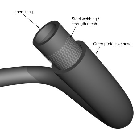
Ah the humble rubber hose. Only on your brake lines, not so
humble. I don't recommend this but if you were to get under your car and cut one
of your hoses in half, you'd notice a couple of things. First, it's amazing how
quick all the brake fluid that spills out will stain your clothes and literally
eat the paint off your car right in front of you. But second, and more
importantly, the hose itself is actually made of three parts. The inner liner is
a corrosion and brake-fluid resistant compound designed (normally PTFE / Teflon®
based) purely to keep the brake fluid in. Around the outside of that, there's a
steel webbed mesh. This is what gives the brake hose its strength and stops it
from bulging and deforming. And around the outside of that there's a slightly
thicker rubber coating, which is there to weatherproof the steel mesh. The three
layers together give strength, flexibility and durability.
Steel-braided hoses.
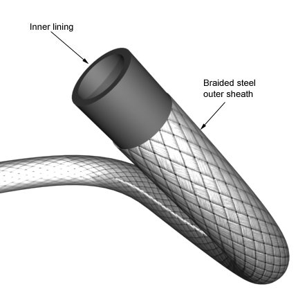
Steel-braided hoses are a slightly different design. They only
really have two components - the inner hose which carries the brake fluid and is
lined with a PTFE compound, and the outer steel braid which contains and flexing
or bulging. Steel-braided lines resist bulging a lot better which is why a lot
of aftermarket tuners opt to put them on their vehicles. One downside is that
the steel braiding itself is totally merciless and if it finds something to rub
against in the vehicle, it will rub right through it, even if it's an alloy. For
that reason, a lot of braided brake hose manufacturers put a third layer - a
thin transparent rubber sheath around the outside simply to keep everything in
check and prevent scuffing and rubbing.
I upgraded the lines on my Audi when I still owned it and put Goodridge steel
braided hoses on. For a 15 year old car it did make a difference to the feel of
the brake pedal. It didn't bring it up to modern standards, but it was better
than the flexible, bendy rubber hoses that were on it from the factory.
Brake fluids.
 As
mentioned elsewhere on the page, brake fluid does not compress. It's a good job
too - if you put your foot on the brake pedal and it went all the way to the
floor, you'd be worried. But that's exactly what can happen if you disregard the
"health" of your brake fluid.
As
mentioned elsewhere on the page, brake fluid does not compress. It's a good job
too - if you put your foot on the brake pedal and it went all the way to the
floor, you'd be worried. But that's exactly what can happen if you disregard the
"health" of your brake fluid.
Brake fluid is hygroscopic - that means it attracts and soaks up water. This is
why it comes in sealed containers when you buy it, and why when the crazy guy
four doors down offers you some of the 15 gallons of brake fluid he's had in his
garage since the war, you should turn him down. The problem with it being
hygroscopic is that if it does start to take on water, Bad Things can happen.
Pull up a chair and allow me to explain.
Your typical DOT 4 brake fluid (see later for DOT ratings) boils at about 446°F
(230°C). Water boils at 212°F (100°C). Imagine your brakes are getting hot
because of a long downhill stretch. Whilst the brake fluid is quite OK, the
temperature of the brake components might get up over the boiling point of
water. If that happens, the water boils out of the brake fluid and forms steam -
a compressible gas. Next time you put your foot on the brake, rather than
braking, all the pressure in the brake system is taken up with compressing the
steam. Your brakes go out, you don't stop.
Getting a little more complex, the boiling point of a liquid goes up with its
pressure (Physics 101). So when you step on the brake, the boiling point of the
brake fluid might actually go up to 500°F (260°C) and the boiling point of the
water content might raise up to 250°F (121°C). This is great, you might think,
because now the boiling point is higher than the temperature of the brake fluid.
At least it is until you take your foot off the brake again. Now the pressure in
the system returns to normal, the boiling points revert to normal and instantly
the water boils off into steam again. The symptoms are slightly different now.
Under this scenario, the brakes work the first one or two times, but on the
third or fourth press, they stop working because now the temperature and
pressures have conspired to boil the water.
The worst possible scenario is brake-fade (see right at the top) combined with
air in the system. If this has happened to you, then you're likely reading this
page from beyond the grave, because in most accidents where weak brakes become
no brakes, there aren't any survivors.
D.O.T ratings
All brake fluids are DOT rated. Your owners handbook for your
car or motorbike probably tells you to use DOT3 or DOT4 from a sealed container.
The DOT ratings are a set of minimum standards the fluid must adhere to
in order to get the rating, and thus work in your braking system. The following
table shows the various properties of DOT ratings. Remember that the values here
are the minimum values. Most manufacturers make sure their product far exceeds
minimum ratings.
| Boiling Point |
DOT 3 |
DOT 4 |
DOT 5 (silicone-based) |
DOT 5.1 (non-silicone based) |
| Dry |
401°F |
446°F |
500°F |
500°F |
| Wet |
284°F |
311°F |
365°F |
365°F |
The "dry" and "wet" boiling points in the table above are for
brake fluid which is fresh from the bottle (dry) and which has a 10% water
content (wet). A DOT study in 2000 discovered that on average, the brake fluid
in a vehicle absorbs about 2% water every 12 months.
The two types of brake fluids shown in the table are DOT3/DOT4/DOT5.1 which are
glycol (Polyalkylene Glycol Ether) based, and DOT5 which is silicone based. DOT3
and DOT4 fluids are interchangeable - the only real difference is their boiling
point. Theoretically you could interchange DOT4 and DOT5.1 fluids too but I
wouldn't recommend it. DOT3/4/5.1 and DOT5 fluids cannot be mixed or
interchanged under any circumstances. They mix like oil and water (ie. they
don't) and the silicon based fluids can destroy the seals in brake systems which
rely on the moisturiser additives that are present in DOT3/4/5.1 fluids.
Other things you ought to know about silicone based fluids:
- they are resistant to absorbing water, which is why their wet boiling points
are so high. Problem is that any water content eventually pools in the low spots
of the brake system and causes rust.
- they don't strip paint.
- they are not compatible with most ABS system because they doesn't lubricate
the ABS pump like a glycol based fluid.
- putting this fluid in systems which have had DOT3/4 fluid in will cause the
seals in the caliper and master cylinders to malfunction. Which means they need
replacing. Which is expensive.
Oh, and don't ask me why DOT5.1 is glycol and DOT5 is silicon based. It doesn't
make and sense to me either.
Brake warning lights
 Most cars
nowadays have a brake warning light on the dash. Its purpose is to alert you
that something is wrong in the braking system somewhere. If it comes on, check
your owner's manual to find out its meaning. Unlike the single-purpose ABS
warning light, the brake warning light doesn't have a standard meaning; it could
be used for multiple purposes. For example, the same light may be used to show
that the hand brake (parking brake for the Americans amongst you) is on. If
that's the case and you're driving, you ought to have noticed the smell of
burning brake dust by now. The light can also indicate that the fluid in the
master cylinder is low. Each manufacturer has a different use and standard for
this light. Which is nice. Because it would be such a drag if the same indicator
meant the same thing in every vehicle.
Most cars
nowadays have a brake warning light on the dash. Its purpose is to alert you
that something is wrong in the braking system somewhere. If it comes on, check
your owner's manual to find out its meaning. Unlike the single-purpose ABS
warning light, the brake warning light doesn't have a standard meaning; it could
be used for multiple purposes. For example, the same light may be used to show
that the hand brake (parking brake for the Americans amongst you) is on. If
that's the case and you're driving, you ought to have noticed the smell of
burning brake dust by now. The light can also indicate that the fluid in the
master cylinder is low. Each manufacturer has a different use and standard for
this light. Which is nice. Because it would be such a drag if the same indicator
meant the same thing in every vehicle.
 If you've got
an ABS-equipped car, you also have a second light - the ABS light. If it comes
on, get it seen to as soon as possible. It means the ABS computer has diagnosed
that something is amiss in the system. It could be something as simple as dirt
in one of the sensors, or something as costly as an entire ABS unit replacement.
Either way, if that light is on, then you, my friend, have got 1970's brakes.
It's important to note that this light normally comes on when you start the car
and then switches off a few seconds later. If it stays on, blinks, throbs,
flashes or in any other way draws your attention to itself, take note. It's not
doing it just to please itself.
If you've got
an ABS-equipped car, you also have a second light - the ABS light. If it comes
on, get it seen to as soon as possible. It means the ABS computer has diagnosed
that something is amiss in the system. It could be something as simple as dirt
in one of the sensors, or something as costly as an entire ABS unit replacement.
Either way, if that light is on, then you, my friend, have got 1970's brakes.
It's important to note that this light normally comes on when you start the car
and then switches off a few seconds later. If it stays on, blinks, throbs,
flashes or in any other way draws your attention to itself, take note. It's not
doing it just to please itself.