| |
|
|
|
|
| |
ARC WELDING WITH CONTINUOUS WIRE
ELECTRODE WITH GAS SHIELD (G.M.A.W.) OR WITHOUT GAS SHIELD
(FLUX or SELF-SHIELDED WIRE).
|
|
| |
|
|
|
|
| |
A. Introduction |
|
|
|
| |
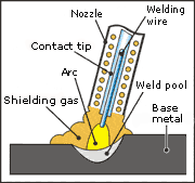
Continuous wire
welding in a shielded atmosphere is often identified by the abbreviations
M.I.G. (Metal Inert Gas) and M.A.G. (Metal Active Gas) or G.M.A.W. (Gas
Metal Arc Welding). Continuous wire welding is a process in which the heat
required to carry out the weld is supplied by an electric arc that is
maintained between the piece to be welded and the wire electrode. The
welding zone is constantly fed with the welding material (the wire
electrode) by means of a special torch, which also supplies the flow of
gas (or gas mixture) whose purpose is to shield the wire electrode, the
weld pool, the arc and the area surrounding the base material from
atmospheric contamination. The presence in the welding circuit of the gas
cylinder (inert or active gas, or a mixture of the two) together with the
use of solid wire electrodes, identifies the gas shield welding process (M.I.G.
or M.A.G.).
The absence of the gas cylinder from the welding
circuit, together with the use of tubular wire electrodes, identifies the
welding process without gas shield (SELF SHIELDED WIRE, NO GAS or FLUX);
in this case the gas shield is obtained by the action of the flux core
contained in the wire. |
 |
|
| |
|
|
| |
|
|
|
|
 |
B. The
welding circuit
The welding circuit consists essentially of the
following elements:
|
|
| |
 |
1. Power source
2. Torch with cable bundle
3. Wirefeeder
4. Water cooling unit
5. Gas cylinder with regulation system
6. Clamp with earth cable
|
|
| |
|
|
|
|
| |
1. power source |
|
|
|
| |
The purpose of the power
source is to feed the welding zone with the welding material, by means of
a special torch, and to maintain the electric arc that is struck between
the piece to be welded and the consumable wire electrode.
Unlike M.M.A. and T.I.G power sources, where there is
only one regulating parameter (welding current), on M.I.G.-M.A.G. power
sources there are two regulating devices, one which regulates electric arc
intensity (welding voltage), and another which regulates the rate of
welding wire feed (welding current).
Power sources can be divided into two categories: |
|
 |
|
| |
|
|
|
|
| |
a)
direct current (DC) power sources
direct current power sources are the commonest power
sources and are characterised by their high stability; this is because
they are based on the fact that an electric arc will tend to stabilise
naturally if it is powered at constant voltage and generated on a wire fed
at a constant rate. Given the flexibility of the process, there is some
flexibility in the choice of voltage and wire feed rate parameters. In
this way it is possible to obtain drop transfer, from the welding material
to the material to be welded, using either the "short arc" immersion
procedure or the "spray arc" procedure. |
|
| |
|
|
|
|
| |
|
|
|
| |
|
|
|
|
| |
b)
pulsed current power sources
in this case it is not the voltage size that is
regulated in the power source, but the current, which is not held constant
but modulated with a train of impulses (hence the name "pulsed"). The
purpose of the impulses is to force the drop to detach itself from the
welding material; in this case the arc is not stabilised naturally, so
that the impulses and wire feed rate must be perfectly synchronised to
achieve an acceptable weld.
Both the in first and second case, at least two knobs
are used for regulation; recent research in the industry has led to the
development and marketing of "synergetic" type welding machines in which
the operator uses only one control knob.
The manufacturer memorises the optimal welding
parameters in the power source and these can be recalled and/or corrected
by the operator, depending on the particular job requirements.
The different polarities when connecting the poles of
the power source to the material to be welded identify two operating
modes: |
|
| |
i)
direct current with straight polarity connection
With electrode negative connection, the torch is
connected to the negative pole and the material to be welded to the
positive pole of the power source; this type of connection is only used in
welding with tubular wire (FLUX). |
|
| |
ii)
direct current with reverse polarity connection
When welding with this operating mode, the torch is
connected to the positive pole and the piece to be welded to the negative
pole of the power source; this is the most frequently used type of
connection. |
|
| |
|
|
|
|
| |
2. torch with cable
bundle |
|
|
|
|
The torch, which
is used to transfer the welding metal to the welding zone, has an
externally insulated body and allows the passage of the wire electrode,
the gas and the welding current |
|
| |
. Its handgrip contains a
control button for switching on the current, gas output and wire electrode
feed.
The cable bundle consists of a current conductor,
control cables, the gas pipe, cooling water circulation pipes (if present)
as well as the wire-guide sheath. There is a variety of different types of
welding torches and pistols available on the market. |
|
|
| |
Water-cooled
torches are used when the current intensity used is such that it generates
a considerable amount of heat energy; they are used for working currents
of over 300 A or for pulsed currents.
Self-cooled torches are cooled by the gas shield and
are used when the working current is below 300 A; these are very commonly
used.
Swan neck torches are also cooled by the gas shield
and are used for low intensity current applications (immersion transfer –
short arc). |
|
| |
|
|
|
|
| |
3. wirefeeder |
|
|
|
| |
The wirefeeder device is
powered by a motor whose job is to push the wire electrode, initially
wound round a reel, towards the torch and hence to the welding zone. The
choice of wire feed rate value is made by adjusting the motor regulator; a
given wire feed rate implies a certain melting rate and hence a defined
value for the welding current. A distinguishing property of a wire puller
is the number of wire-feeder rollers; devices with 4 rollers feed the wire
more uniformly with respect to those with 2 rollers. |
|
|
| |
|
|
|
|
| |
| |
4.
water cooling system |
|
|
| |
The water
cooling unit is a device used to cool the torch, if it is water-cooled,
should the high welding currents used cause excessive overheating. A pump
ensures continuous circulation of water in the torch and, by means of a
cooling system, controls overheating.
|
|
|
| |
|
|
|
|
| |
5. gas
cylinder with regulation system |
|
| |
The cylinder
contains the shield gas/gases such as argon, helium, carbon dioxide or
mixture of them, and is fitted with a pressure gauge with related pressure
reducer, which is used to indicate the quantity of gas in the cylinder. It
is also fitted with a solenoid valve, which are controlled by a button on
the torch, to open and close the gas flow as welding is started or ended.
|
|
| |
|
|
|
|
| |
6. clamp with earth
cable |
|
|
|
| |
The clamp with
earth cable is used to make the electrical connection between the power
source and the base material to be welded. The section and length of the
cable are determined by the maximum current from the power source.
|
|
|
| |
|
|
|
|
| |
C. The shield gases |
|
|
|
| |
The shield gases
used in M.I.G.-M.A.G. welding procedures can be divided into two basic
categories: inert and active. Argon, helium and argon-helium mixtures
belong to the first type, while carbon dioxide and argon/oxygen or
argon/carbon dioxide mixtures are considered active gases.
Argon (Ar) is an
inert gas, produced by fractional distillation of the atmosphere. The gas
is extracted from the air and may, therefore, contain traces of impurities
such as oxygen, nitrogen or water vapour, but it is nevertheless
considered suitable for most welding applications.
The use of this gas in M.A.G. applications gives good
arc stability and an easy strike. Moreover, given its low thermal
conductivity, the central part of the arc column remains at a high
temperature giving more fluidity to the drops of material passing through
the arc zone.
Helium (He) is an
inert, rather rare gas that is scarcely present in the atmosphere and is
extracted from underground: it is therefore much more costly than argon.
Compared to argon, helium has a less stable arc but
greater penetration; it is mostly used for thick welds and for materials
with high thermal conductivity, such as, for example, copper and
aluminium.
Since helium, unlike argon, is lighter than air and
hence more volatile, a greater quantity of gas is needed to ensure a
sufficient shield for the welding zone.
Carbon dioxide (CO2)
is an active gas, present in the air and underground. The commonest
problem caused by this type of shield is that it can cause the formation
of excessive spray and establish an unstable arc; if the arc is kept
rather short and of constant length, however, it is possible to keep it
under control. With a CO2 shield good penetration is generally obtained.
Active mixtures.
It is often possible to take advantage of the qualities of individual
gases, by using a mixture for the gas shield e.g. argon-oxygen,
argon-oxygen-CO2, argon-CO2.
Even if the inert gases in their pure state are able
to perform their shielding effect at any temperature, the addition of
active gases improves arc stability and the transfer of the wire electrode
metal to the weld pool. This occurs without impairing the shielding
effect. |
|
| |
|
|
|
|
| |
D. Welding wires |
|
|
|
| |
The wires can be
identified by their chemical composition and also their section
morphology, which may either consist of a single metal (solid wires) or
have an internal core containing granules (tubular wire).
Particular attention should be paid to the presence
of grease or moisture on the surface of the wire electrode, because they
could cause cracks, porosity or blowholes; in addition, if the wire
electrode reel is not wound uniformly this could cause uneven wire feed
resulting in unstable welding |
|
|
| |
Solid
wires usually have the same composition as
the base material, with added elements able to help clean the base
material. The most widely used diameters are 0.6 – 0.8 – 0.9 - 1 – 1.2 –
1.6 mm.
Tubular wires,
with gas shield, do not consist of solid metal but have an internal core
filled with granular powder (flux); this has the same functions as the
coating on coated electrodes.
The granular powder or flux can be of rutile, basic
or special type.
Compared to solid wires, tubular wires have better
arc stability and deeper penetration, ensure a better-looking seam, often
eliminating the need for further finishing (e.g. spray grinding) and
reducing the risk of defect formation, such as porosity; of course the use
of tubular electrodes requires slag removal, as for welding with M.M.A.
electrodes.
The most widely used diameters are 0.6 – 0.8 – 0.9 –
1.2 – 1.6 mm. |
|
| |
|
|
| |
E. The
welding metal: transfer methods |
|
| |
With
M.I.G.-M.A.G welding procedures, the method of transferring the welding
metal from the wire electrode (either solid or tubular) to the weld pool
depends, as well as on the electrical welding parameters, on the wire
diameter, the type of power source and the gas used. Depending on these
parameters, drop transfer may be by:
1. Immersion (short-arc, dip-transfer or short
circuit)
2. Spray-arc
3. Impulse or pulsed-arc |
|
| |
|
|
| |
1.
immersion transfer (short-arc, dip-transfer or short circuit)
The welding metal is transferred to the weld pool in
the form of drops which are immersed in the pool itself, creating
continuous short circuits.
This "short arc" transfer is characterised by the
presence of current intensities of up to 200 A, by the use of thin solid
wires, from 0.6 m to 1.2 mm, enabling thin welds and welding in all
positions possible. This is obtained using direct current power sources.
|
|
| |
2.
spray-arc transfer
This method is designed so that the drops of material
are not transferred to the weld pool by contact but rather, due to the
effect of the high current, are sprayed into the bath creating a
continuous flow of material.
This feature is obtained using direct current power
sources when the current used is high (greater than 200 A) and the wires
have a diameter of more than 1 mm. A very fluid weld pool is generated,
with sizeable penetration, which is suitable for horizontal welding of
mainly medium and large thicknesses. |
|
| |
|
|
|
|
| |
3.
pulsed-arc transfer
This procedure can only be obtained with pulsed
current power sources. The pulsations actually cause small-sized drops to
detach themselves and therefore the typical spray arc is obtained, even
with low currents. Heat generation/contribution, pool size and penetration
are similar to those achieved with the spray arc method. This procedure is
most often used for materials such as aluminium or stainless steel, for
which the short arc welding procedure cannot guarantee sufficiently high
quality results. |
|
| |
|
|
|
|
| |
F. Materials
welded by M.I.G./M.A.G. |
|
| |
1.
mild, carbon steels
Carbon steels are welded with direct current and
electrode positive polarity (the wire electrode is connected to the
positive pole) using exclusively the M.A.G. welding procedure.
Applications may range from the use of CO2 only, to argon - CO2 mixtures
in differing proportions (the most common is 80% argon, 20% CO2 ).
The greater the percentage of argon in the mixture
the better the properties and arc stability.
The weld has very good properties, especially with
short arc where dense/thick weld pools are obtained, allowing welding in
all positions.
The use of wires with silicon and manganese content
will lead to the elimination of impurities present in the base material
and obtain good quality welds.
Bevelled seams should be prepared with thicknesses
greater than 3 mm. |
|
| |
|
|
|
|
| |
2.
stainless steels
Stainless steels are welded with direct current and
electrode positive polarity (the wire electrode is connected to the
positive pole) using exclusively the M.A.G. welding procedure.
The gas shield used should consist of Ar + CO2 or Ar
+ Oxygen mixtures. The proportion of argon in the mixture should never
fall below 98% so as to avoid strong oxidation of the chrome present in
the base material.
Seams thicker than 2.5 mm should be bevelled. Care
should be taken to choose the most suitable welding material for the
quality of the stainless steel being welded.
To achieve a good weld, we advise grinding the spots. |
|
|
| |
|
|
| |
|
|
|
|
| |
3.
aluminium and its alloys
Aluminium and its alloys are welded in direct current
or pulsed current with electrode positive polarity (the wire electrode is
connected to the positive pole) using the M.A.G. welding procedure.
The gas shield used is usually pure argon. Pure
helium or an argon + helium mixture can also be used.
For horizontal welding, irrespective of the
thickness, the spray-arc and/or pulsed-arc technique is used; the
short-arc technique is used, instead, on thin vertical or corner welds.
Given the properties of aluminium, milling the spots instead of grinding
is advisable. |
|
| |
|
|
|
|
| |
4.
other materials
The M.I.G.-M.A.G. welding procedure is also used on
materials such as nickel and its alloys, copper and its alloys; for all
these materials direct current with electrode positive polarity is used.
For welding copper more than 5 mm thick we advise
adoption of the M.I.G. procedure but in any case the current intensity
should be adjusted according to the welding position and the seam
thickness. |
|
| |
|
|
|
|